
Description
Description
QTR-8A Reflectance Sensor Array 8 channel Line Following Line Tracking Sensor Module
8 channel Reflectance Sensor Array
Specifications
- Dimensions: 2.95″ x 0.5″ x 0.125″ (without header pins installed)
- Operating voltage: 3.3-5.0?V
- Supply current: 100?mA
- Output format: 8 digital I/O-compatible signals that can be read as a timed high pulse
- Optimal sensing distance: 0.125″ (3?mm)
- Maximum recommended sensing distance: 0.375″ (9.5?mm)
- Weight without header pins: 0.11?oz (3.09?g)
The module is a convenient carrier for eight IR emitter and receiver pairs evenly spaced at intervals of 0.375″ (9.525?mm).
Functional Description
The QTR-8A reflectance sensor array is intended as a line sensor, but it can be used as a general-purpose proximity or reflectance sensor. The module is a convenient carrier for eight IR emitter and receiver (phototransistor) pairs evenly spaced at intervals of 0.375″ (9.525?mm). Each phototransistor is connected to a pull-up resistor to form a voltage divider that produces an analog voltage output between 0?V and VIN (which is typically 5?V) as a function of the reflected IR. The lower output voltage is an indication of greater reflection.
The outputs are all independent, but the LEDs are arranged in pairs to halve current consumption. The LEDs are controlled by a MOSFET with a gate normally pulled high, allowing the LEDs to be turned off by setting the MOSFET gate to a low voltage. Turning the LEDs off might be advantageous for limiting power consumption when the sensors are not in use or for varying the effective brightness of the LEDs through PWM control.
The LED current-limiting resistors for 5?V operation are arranged in two stages; this allows a simple bypass of one stage to enable operation at 3.3?V. The LED current is approximately 20-25?mA, making the total board consumption just under 100?mA. The schematic diagram of the module is shown below:
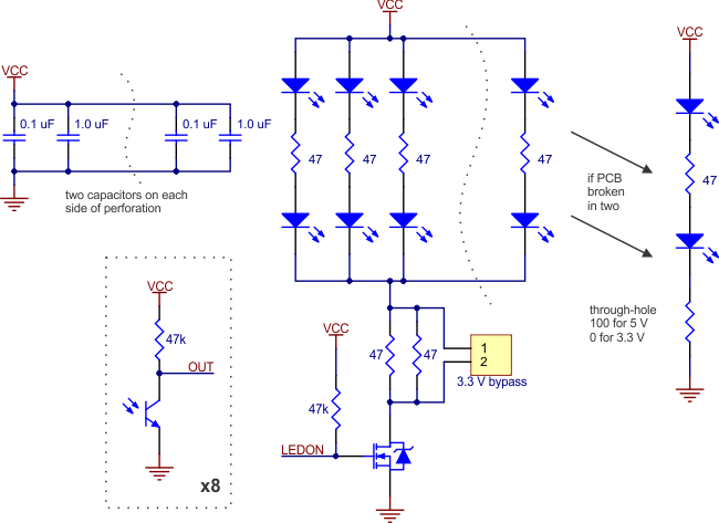 |
Interfacing with the QTR-8A Outputs
There are several ways you can interface with the QTR-8A outputs:
- Use a microcontroller?s analog-to-digital converter (ADC) to measure the voltages.
- Use a comparator with an adjustable threshold to convert each analog voltage into a digital (i.e. black/white) signal that can be read by the digital I/O line of a microcontroller.
- Connect each output directly to a digital I/O line of a microcontroller and rely on its internal comparator.
This last method will work if you are able to get high reflectance from your white surface as depicted in the left image, but will probably fail if you have a lower-reflectance signal profile like the one on the right.
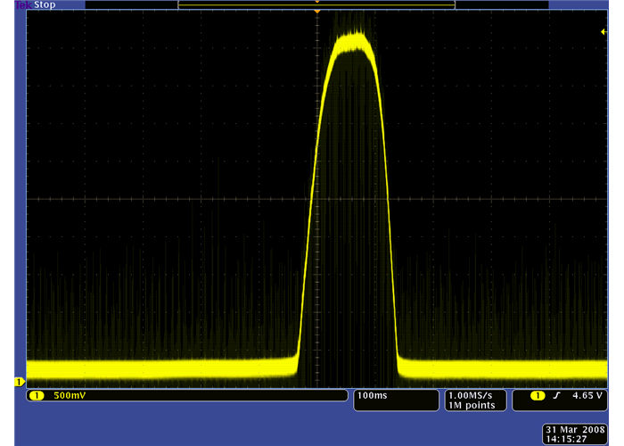 QTR-1A output 1/8″ away from a spinning white disk with a black line on it |
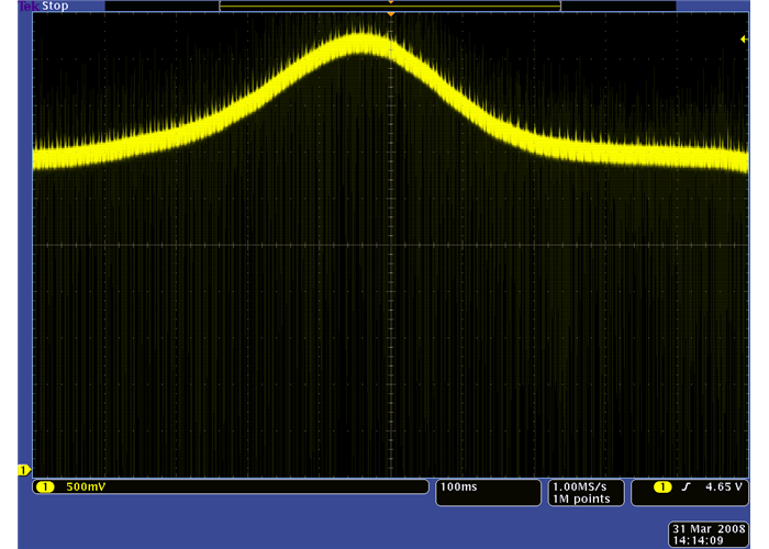 QTR-1A output 3/8″ away from a spinning white disk with a black line on it |
Reviews
No posts found


Reviews
There are no reviews yet.