
Description:
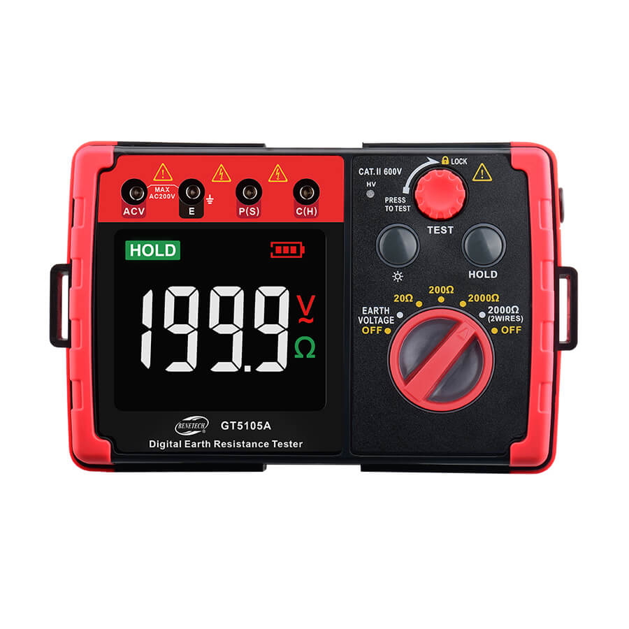
The GT5105A Earth Resistance Tester is a digital instrument from Benetech that accurately measures grounding resistance and ground voltage. In addition, it evaluates the grounding of various electrical systems, including power facilities, electrical equipment, and lightning protection systems. Furthermore, the tester supports both precise three-wire measurements and simpler two-wire measurements, so that users can select the method that best fits their needs. As a result, it delivers reliable and accurate readings, therefore ensuring safe and efficient electrical installations.
Key specifications:
- Measurement functions: Earth Resistance and Earth Voltage.
- Earth resistance range: 0 to 2000Ω, with selectable ranges of 20Ω, 200Ω, and 2000Ω.
- Earth voltage range: 0 to 200V AC.
- Display: A large digital LCD screen with a backlight for easy reading.
- Accuracy:
- 20Ω range: ±(2% + 10 digits) with 0.01Ω resolution.
- 200Ω range: ±(2% + 3 digits) with 0.1Ω resolution.
- 2000Ω range: ±(2% + 3 digits) with 1Ω resolution.
- Safety features: Double insulation and reinforced insulation safety structures.
- Data features: Data hold function and storage for up to 20 sets of data.
- Power supply: 6 x 1.5V AA alkaline batteries.
How to use the GT5105A (3-wire method)
The three-wire method measures grounding resistance precisely. Before you start, first inspect the equipment’s insulation and ensure that the tester’s battery is fully charged. Additionally, check all connections carefully, so that you can avoid errors during measurement. Furthermore, following these steps helps you obtain accurate and reliable readings.
- Placement: Drive the two auxiliary grounding nails (electrodes) into the earth in a straight line away from the main earth connection under test.
- Electrode P (potential electrode) is placed at a distance from the earth connection.
- Electrode C (current electrode) is placed further away from electrode P.
- For reliable results, ensure the electrodes are inserted into moist soil. If the ground is dry, add water to dampen it.
- Connection:
- Connect the E terminal (green wire) on the tester to the main grounding point.
- Connect the P terminal (yellow wire) to the potential electrode.
- Connect the C terminal (red wire) to the current electrode.
- Measurement:
- Set the appropriate resistance range (20Ω, 200Ω, or 2000Ω).
- Press the “Test” button to initiate the measurement. The tester will display the resistance reading.
- Troubleshooting:
- The LCD will display “—- Ω” if a test lead is not properly connected.
- “OL” indicates the resistance measurement is over range.
Applications:
- Power and electrical systems: Measuring grounding resistance for equipment and wiring.
- Lightning protection: Testing the effectiveness of lightning protection equipment.
- General grounding devices: Verifying grounding for any facility with a grounding device.


Reviews
There are no reviews yet.